Solution
Split SignalsSignals are extracted from the Split Signals Express VI in the same order that they were merged together. This means that if you create a combined signal from 3 individual signals (using the Merge Signals Express VI) and you later want to retrieve only the third signal, you must resize the Split Signals Express VI to have three outputs.Then, use the output from the third (last) terminal. If you want to retrieve the second signal, only two outputs are needed and you would use the second output terminal.
Note: LabVIEW does allow you to expand the Split Signals Express VI to have more outputs than the number of individual signals present. However, the extra outputs do not return any data.
Split Signals Express VI is especially useful when you are using a DAQ Assistant that acquires data from multiple channels. When you have your DAQ Assistant configured to sample multiple channels, you can wire the Dynamic Data Type from the output of the DAQ Assistant to the Split Signals Express VI. You must resize the Split Signals Express VI to the number of channels you are sampling. This is done by grabbing the bottom of the VI and dragging down until you have the desired number of outputs. The signals go in order, so the first channel configured in the DAQ Assistant is the top most in the Split Signals Express VI. You can now wire graph indicators to each of the outputs to be able to view each signal individually. The picture below shows what the code might look like.
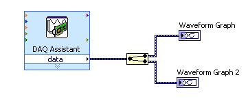 Figure 1.
 Split Multiple Channel Signals from DAQ Assistant
When you wire a signal output to the wire branch of another signal, a Merge Signals Express VI is automatically created on your block diagram. The placement of the Merge Signals Express VI, however, is dependent on the direction you wire the signals. For example, if you wire signal output B to the wire branch of signal A, the Merge Signals Express VI is created at signal A, as shown below.
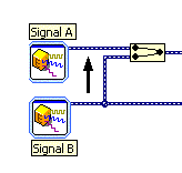 Figure 2.
 Merge at Signal A
However, if you wire signal output A to the wire branch of signal B, the Merge Signals Express VI is created at signal B.
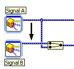 Figure 3.
 Merge at Signal B
You can also use the Merge Signals Express VI to add another signal to two or more signals that are already merged together. Take the picture below, for example.
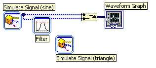 Figure 4.
 Existing Merged Signals
If you wire the new signal directly to the existing Merge Signals Express VI, an additional input is created for you automatically, as shown below.
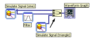 Figure 5.
 Wire to Existing Merge Signals VI
However, if you wire the new signal to the wire branch of one of the existing signals, a second Merge Signals Express VI is created.
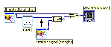 Figure 6.
 Wire to the Branch of Existing Signals
Note: The final output to the Waveform Graph will be the same in both cases.