First place down all your components.
- "ctrl + w" opens up the component window. form there you can place down your components.
- AC_POWER and Ground can be found under Sources>Power_Sources.
- Diodes can be found under Diodes, for this example were using a Virtual diode.
- Resistors can be found under Basic>Resistors. for this example were using a 1K ohm resistor.
- Use "ctrl+shift+W" to wire the components together.
- Adjust the values on the Voltage source by double clicking it and navigating to the value tab, from here we can edit the values of the source. we have used 10V RMS and 5Hz for this example.

When done the circuit should look something like this.
Now we can start taking our measurements.
- Navigate to your Oscilloscope on the left hand side of the screen.

2. Click and drag your
Oscilloscope to a wanted possession on work space
3. Connect the two ports from the
A Terminal to the circuit, positive on top and negative on bottom of the
resistor.

4. Run the simulation by pressing the
green Triangle, in the
simulate toolbar, or by pressing the
F5 key on
your keyboard. Make sure you run the simulation in interactive mode. this can be altered under
Simulation>Analysis and Simulation.
5. To access your
Oscilloscope readings toy can
double click on the
oscilloscope icon on your work space. This
will bring up your standard waveform chart.
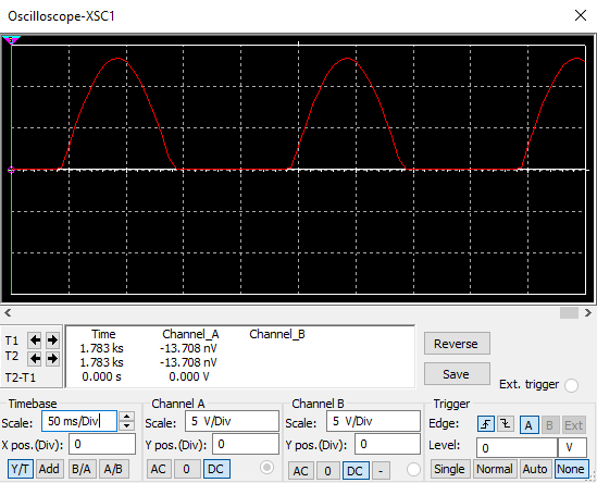
6. You can increase the scale of the
X-axis (time) under the
Timebase section of the
oscilloscope, for this
example
50 ms/DIV should be sufficient.This will give you a wave similar to the one displayed below.
7. Now
Pause (
F6) or
Stop your simulation, under the simulation toolbar. this will allow us to take accurate
measurements using the oscilloscope cursors, these can be moved by click and drag, or by using the arrows
besides
T1 and
T2. The Values of the cursors are displayed underneath the graph.
