There is some way to compensate for the voltage drop like remote sensing, shunt calibration, and equation. However, NI 9219 supports none of these methods in only full-bridge strain gage. So you need to use roundabout methods.
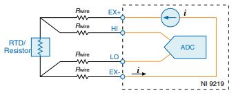
- Measurement with 4-wire resistance and 4-wire RTD circuitry
In this case, lead wire resistance does not affect these measurement types as the NI 9219 sources a current. If you know all resistance of full-bridge, you can measure Vex across the full-bridge.
- Set AI Resistance in polymorphic VI selector of DAQmx Create Virtual Channel.vi.
- Select 4-wire in Resistance Configuration.
- Add a calculation. You can get an exact strain. (This solution works only for full-bridgeⅠ,Ⅱ)

If you want more information related to the above, please refer to additional information.
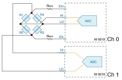
- Realization of remote sensing by using other channels
If you measure Vex on another AI channel, it can read an exact Vex. Then, you are able to get a correct strain by adjusting an exact Vex.
- Direct compensation to the measured strain value
When you know the lead wire resistance and nominal gage resistance, you can directly compensate for the strain value output from DAQmx Read.vi. But you can not compensate for voltage drop caused by the temperature of lead wire resistance. (This solution works only for full-bridgeⅠ,Ⅱ)

If you want more information related to the above, please refer to additional information.
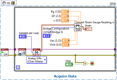
Minimizing the lead wire resistance, use an external voltage source with a short wire. You can get a strain value using Convert Strain Gauge Reading.vi with adding needed parameters.

Additional Information
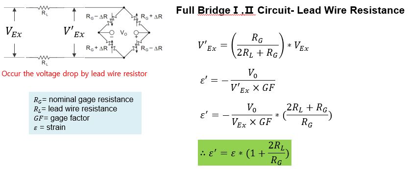
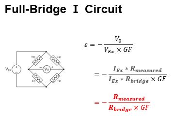
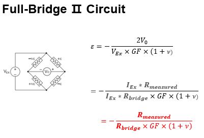
The calculation used in solution 1 is below.

The calculation used in solution 3 is below.