Solution
Inductive loads make up a family of devices that have windings of conductors as an integral part of their design. Examples of inductive loads include relay coils, motors, and solenoid coils. These types of loads need to be treated properly when switching because they store energy when current is passed through them. This energy has to go somewhere when the inductive load current is interrupted. If there is no alternate path for the current, a high voltage will develop until there is a breakdown of dielectric and arcing occurs. This voltage can be quite high and is governed by the equation V = L (dI/dt), where V is the voltage across the inductance, L is the inductance of the load, and (dI/dt) is the rate of change of current with respect to time. The more quickly the current is changed in the inductance, the higher the voltage will go. This high voltage, or flyback voltage, can cause interference which in turn can cause unwanted behavior in the device doing the switching or devices in close proximity. The high voltage and stored energy can also degrade the contacts of the relay which can greatly reduce the expected product lifetime requiring sooner than expected maintenance or replacement of the switch module.
Flyback voltage can be limited in different ways. The methods used will vary depending on the DC or AC nature of the circuit.
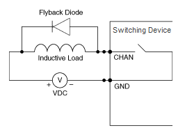 Figure 1: DC Inductive Loads
 Figure 1 shows an inductive load (e.g. solenoid, relay coil, motor, etc.) with a diode placed across it. This diode provides a path for the inductor current to flow when the current is interrupted by the relay. Without this diode, the voltage across the coil will be limited only by dielectric breakdown voltages of the circuit or parasitic circuit elements of the coil. This voltage can be kilovolts in amplitude even when nominal circuit voltages are low (e.g. 5 V).
The diode should be chosen so that the reverse breakdown voltage is greater than the voltage driving the inductive load. The voltage rating of the diode can be found by looking at “VR”, the DC blocking voltage, in the datasheet. The current rating should be equal to or greater than the maximum current flowing through the load. This is the “Forward Current” specification for the diode. The location of this diode should ideally be as close to the load as possible.
Since the power source can be either positive or negative in voltage, a single diode will not work to control possible voltage transients in an AC circuit. A common method of limiting voltage transients uses Metal Oxide Varistors (MOVs). This technique reduces voltage transients to levels defined by the rating of the MOV.
MOVs act to “clamp” voltage transients to predetermined levels. They are very fast acting and go from a very high impedance to a very low impedance in nanoseconds or less. It is important to size the MOV properly, however, for both the voltage at which it breaks down and the energy it must absorb. A rule of thumb would be to set the voltage rating of the MOV at a value 10-25% higher than the nominal system voltage. Another important parameter of the MOV is energy rating. The MOV must be sized to dissipate the energy stored in the load. This may be referred to as the “Load Dump Energy” or “Maximum Absorption”. The units will always be in joules though. MOV vendors will also specify a peak current, Ip.
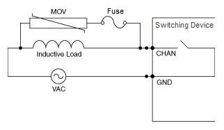 Figure 2: AC Circuit Protection using an MOV
 Other sources of transients exist besides those created by inductive loads. For AC circuits, this can be the power source itself. AC power lines frequently have high voltage transients that should be guarded against. MOVs can be used limit these transients as well.
Like all parts, they can eventually fail. MOVs usually fail as a short circuit. For this reason, it is good practice to include a properly sized fuse in series with the MOV. Figure 2 shows an AC system protected by MOVs. Another effective way to limit high voltage transients is to use a “snubber” circuit. Snubber circuits can be used for either DC or AC applications and provide an alternative to either of the previous methods presented here. Due to the variety of types of snubber circuits and their complexity, this method of transient suppression will not be covered in this KnowledgeBase.