Solution
The +/-10 V specification you see on modules is in reference to
module ground rather than
earth ground. To really understand what your module is capable of measuring, there are two important specs to understand. We will use the NI 9215 module as an example. The first spec to look at is
Maximum Working Voltage. This is the voltage range within which your module can accurately read measurements. In the case of the 9215, this voltage is listed as +/- 10.2 V of
common.
Common is the module common pin, not earth ground. What this means is that as long as the voltage you are trying to read on a channel is within +/-10.2 V of the voltage level of the common pin, you will get back accurate measurements in relationship to the voltage on the common pin.
So can we measure any 20 V range with our 9215? Let's say you want to measure 400 V-420 V. That's where the second spec comes in:
Channel-to-earth Isolation. Channel-to-earth isolation is how much of a voltage difference you can have between any channel and earth ground before you damage the module. In the case of the 9215, channel-to-earth isolation is rated at 250 Vrms when using screw terminals or 60 VDC when using BNC connectors. So 400 V would be out of range. However, we could comfortably measure a 200-220 VDC range using screw terminals. Note that the module will return a voltage of between +/- 10.2 V, so you will need to add on the supply voltage connected to the common pin in order to get the actual voltage.
Low Accuracy/High Voltage Work AroundOften users will tie their module common pin to earth ground, allowing measurement of any voltage that is within +/- 10.2 V of earth ground. However, you do not have to tie the common pin to earth ground. For example, you could set the common pin to 10 V by using a 10 V power supply and connecting the positive lead of the 10 V power supply to the common pin of the measurement module. In this case your module could measure +/- 10.2 V with respect to 10 V, or in other words -.2 V to 20.2 V. You would have to ensure that the 10 V supply connected the common pin is accurate and stable since all of your measurements will be in relation to that voltage. If it drifts, your measurements will as well!
High Accuracy/Low Voltage Work AroundNow let's suppose that the supply voltage we are tying into the common pin of our module is noisy or slightly unstable. Each measurement sample would be off by the amount of noise present in our supply voltage at the time of the sample. If the supply voltage we are tying to the common pin is
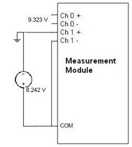
10 V or less one strategy we can use is to use a second measurement channel to actually measure the supply voltage on every sample and add it to our signal measurement. To do this we could plug the ground of the supply into the positive terminal of one of the measurement channels. The negative terminal of this channel would be shorted to the common pin. On every sample we will measure two channels - our signal and our supply ground. The measurement on the supply ground channel will be a negative value since the supply ground is connected to the positive terminal of the measurement channel and the negative terminal is shorted to common, which is of course tied to the power supply voltage. From the original question, we can now measure a 14 V-18 V signal by subtracting the supply ground channel measurement from our signal channel measurement to get the actual measurement.
For example, let's say on a given sample we measure the supply ground channel as -8.242 V, and signal channel as 9.323 V. This tells us that the common pin was at 8.242 V for that sample and that our signal was 9.343 V higher than that. Therefore, our signal is at 9.323 - (-8.242) = 17.565 V at the time of the sample.
As long as you continue to measure earth ground on one of your channels, you don't have to have an accurate power supply, it just needs to stay between 8-10 V for this example. The supply needs to be at least 8 V in this example to continue to measure up to 18 V accurately, and it needs to be less then 10 V so you can measure the supply ground accurately.