NB: If you have a counter module (or other hardware) it is recommended to use that instead to generate a signal instead of using the freqout method.
It is possible to output a digital/counter signal along a chassis PFI line. It is also possible to adjust that signal while the program is running using the DAQmx API. This is achieved using DAQmx property nodes however it may not be possible to do without stopping the DAQmx task. Results vary depending on the hardware being used.
The program below was created for a cDAQ-9178 which does not support adjusting the frequency while the DAQmx task is running. The DAQ is outputting a counter signal for controlling a motor (or a similar device). When changing the frequency on the front panel, there is a delay where no signal is outputted. The length of this delay varies depending on your system specifications.
To create this program complete the following:
- Use a DAQmx Create Channel VI to configure a counter output task for pulse freq generation
- Set the counter channel name input as <Your Device Name>/freqout and the frequency input to a desired value (this value will be changed by property nodes before the task starts). To view the freqout channel, right-click on the constant/control and select I/O Name Filtering. In the dialog box, check the Internal Channels tickbox and click OK.
- For E-Series devices, set the sample mode to Continuous Samples using a SampQuant . SampMode property node. Then follow DAQmx Timing Property»Sample Quantity»Sample Mode.
- For M-Series devices, signals can now be routed to chassis PFI or RTSI line using a DAQmx Channel Propery Node. Select the CO.Pulse.Term property by following DAQmx Channel Property»Counter Output»Pulse»Output Terminal).
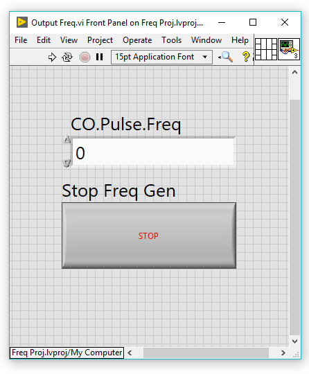
- Create a front panel control to adjust the frequency while the program is running. Create a local variable of this front panel control by right click on the control and select Create»Local Variable. Use the Not Equals? comparator and Shift Registers to compare the current frequency value to the previous value (therefore detecting a change)
- Use While Loops to ensure that the program continues running and restarts the task when the frequency is adjusted
Front Panel
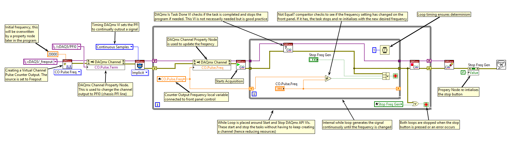
Block Diagram