It is recommended that you have experience with DAQmx functions (gained through our DAQmx Course) before attempting the solutions below. All solutions will be using the DAQmx API to sync hardware. See this link for more information about our DAQ course and its content.
The Different Types of Synchronization
Synchronization between chassis can refers to a variety of different setups including:
- Using the PXI(e)'s External BNC Connector to output a clock.
- Aligning 2 data sets from different chassis together into 1 file.
- DAQ on two chassis begin at the same time by sharing triggers.
- Sharing reference clocks or master timebases.
All of the above are forms of synchronization and provide different levels of accuracy. Some methods require specific hardware while others require only two PXI(e) chassis. A combination of several setups will provide the highest level of accuracy and determinism possible.
Connecting a PXI_CLK10 OUT to a PXI_CLK10 IN - BNC Connectors
This level of synchronization is relatively easy to achieve as it requires no hardware modules. If you are using two chassis you can connect the master's PXI_CLK10 OUT of one chassis, to the PXI_CLK10 IN of another chassis. This will share a common timebase to both PXI(e)s preventing drift. This method can be done for two PXIe chassis, two PXI chassis and a PXIe/PXI combination.
Using the BNC connectors, when a clock is present it will automatically override the PXI system clock. This introduces a very small-time skew between the two-clock waveform that is negligible between two PXI systems but will increase when daisy-chaining chassis. To significantly reduce this skew, use an external 10 MHz clock source with equal length cables going to each PXI_CLK10 IN connector.
This method will sync the system to a low degree. To achieve a higher sync, you require purchasing Timing and Synchronization hardware modules
Trigger Sharing - Requires Timing and Synchronization (T&S) Modules
Trigger sharing will ensure that both chassis begin DAQ at roughly the same time. Each PXI(e) in the system will require a T&S Module which will share trigger lines between the each PXI(e). The example block diagram shown below demonstrates how to sync trigger lines together.
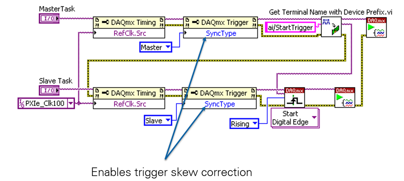
Here a trigger source is defined in the master task (top line of code) and sent to the slave task (bottom line of code). When the trigger is detected the slave task will begin, followed by the master task. This order is essential, the slave must always begin before the master. To correct for the skew caused by one task starting after another, a DAQmx Trigger property node is used to define one channel as master and one as slave.
Combining this sync method with the previous example creates a system without skew or drift; however, both chassis will have to run at the same rate.
Sharing a Reference Clock
A reference clock is a clock signal that is referenced by other systems’ clocks to derive their own clock signals. Sharing this clock between devices will allow each chassis to run at different rates while also minimizing drift and skew. Sharing a reference clock requires a T&S module and can be implemented as shown in the previous image (through using a DAQmx Timing Property node with the same source).
One downside of sharing a reference clock is that for high frequency applications, the clock signal will begin to deteriorate at frequencies around 5-10 MHz (depending upon the cabling used to wire between the external clock source and the boards). In addition, there is a transmission latency that will introduce pronounced phase delays at high speeds depending upon the length of the signal path.
All timing sources will introduce jitter into the system that could become significant when attempting to synchronize the boards. When a start trigger is used to simultaneously begin acquisition on all of the boards in a measurement system. Usually, each board will trigger within 1-2 ticks of the board clock upon receiving the start trigger which will introduce phase delays between boards.
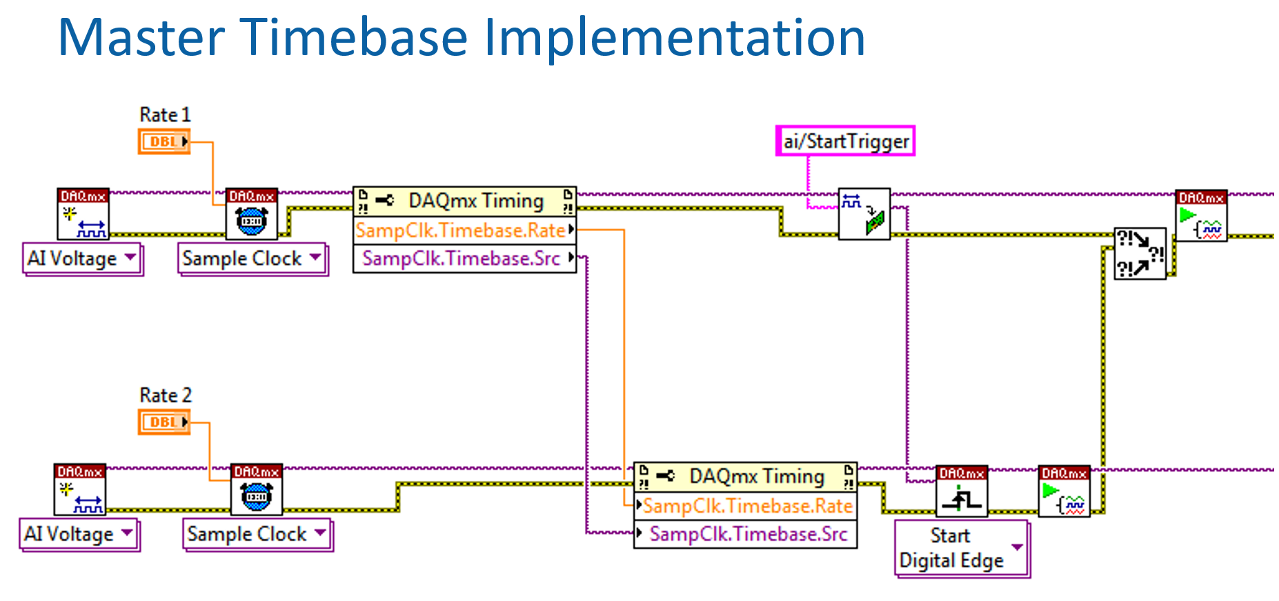
Sharing a Master Timebase
Sharing a master timebase has all the benefits of sharing a reference clock while also eliminating drift. It is shared using property nodes as shown below. The slave's clock will be overwritten by the master's clock meaning that all hardware timed systems will automatically be in sync with the master chassis. Due to the nature of timebase sharing, this system can be erratic so ensure that your system is stable before use.
Additional Information
Achieving the Highest Level of Synchronization Possible
To achieve the highest level of sync, include some form of clock and trigger sharing in your system. A good example of this is to share a reference clock and a trigger between PXI(e)'s using a T&S module.