Solution
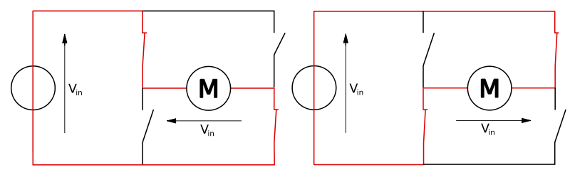
Unfortunately there's no resistance specified for the motor bridge of the module and the reason is that it's a non-linear/non-ohmic circuit. It's basically 4 transistors arranged in such a way that you can choose to output No Voltage, Positive Voltage, or Negative Voltage. The images below replace the transistors with switches, but it shows how the part works.

Above: H Bridge in "off" configuration. Below: H Bridge with current flowing in both directions.
Transistors don't have a resistance, per se, so there will be negligible voltage drop across the transistors in this H-bridge. They will basically act as conductors when in the "on" position.