Routing the output of one counter to the source of another counter should be done using property nodes and/or DAQmx Export Signal.
Routing Example 1 (Property Nodes):
- Create a task for the second counter using the DAQmx Create Channel VI (An example of a basic counter task can be found in the NI Example Finder)
- Before the DAQmx Start Task VI, add a DAQmx Channel property node to the task (if the task is finite, add the property node before the DAQmx Read VI)
-
You can change the source of the signal to measure on the counter circuit from this property node. Go to Counter Input»Measurement Type (i.e. Frequency)»Input Terminal. This is shown in Figure 1.
Note: It is important you pick the proper measurement, because different measurements use the counter circuit different ways. Count edges means the signal being measured is connected to the counter source pin. While period measurement has the signal being measured connected to the gate pin of the counter.
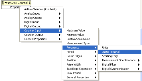 Figure 1: Input Terminal Selection
- Right click on Input Terminal and select Change to Write
- Right click on the input node for Input Terminal and select Create»Constant
- Right click on the input terminal constant and select I/O Name Filtering...
- On the Graphical User Interface that comes up select Include Advanced Terminals.
- Click on the pull down arrow on the constant and select Ctr1InternalOutput. This is assuming you want to connect a signal being generated by Ctr1. Select a different number if you want to route the signal in from a different counter. The channel and terminal setup should appear as in Figure 2. In particular the channel type must match the input terminal type. In this case they are both period.
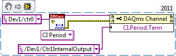 Figure 2: Counter Signal Routing Block Diagram
Other parts of the counter, besides the signal input pin, can be rerouted on the board as well. To see these choices you can check through the channel read and write property nodes to see what aspects of the counter signal and timing can be rerouted. Please also look at the related link about internal route availability.
Routing Example 2 (DAQmx Export Signal):
- Create a task for the first counter (the counter producing the signal you are wanting to route) using the DAQmx Create Channel VI.
- Before the DAQmx Start Task VI, add a DAQmx Export Signal VI (Add this before the DAQmx Read VI if the task is finite)
- Right click the input node called Signal and select Create»Constant
- Click the Signal constant that you just created, select Counter Output Event from the drop down menu
- Right click the input node called Output Terminal and select Create»Constant
- Click the terminal constant you just created and select the PFI line that corresponds to the second counter's input which you are wanting to route the first counter's output to.
Note: DAQmx Export Signal will return an error if you try to export the signal directly to the source or gate of your second counter instead of the PFI line. For example setting the Output Terminal constant to be Dev1/Ctr1Gate instead of Dev1/PFI4 will return an error. To find the default PFI line that corresponds the source or gate of your second counter, refer to the Pinout section of your device's manual, or right click the device in Measurement & Automation Explorer and select Device Pinouts from the drop down menu
 Figure 3: Counter Signal Routing Using DAQmx Export Signal
If you are using multiple devices and need to route counter signals between them, refer to the related link about using DAQmx Export Signal to export the counter signals over RTSI.
- Create a counter input task for the second counter using DAQmx Create Channel VI.
- Set the Counter terminal on DAQmx Create Channel VI to be the counter which you have exported the first counter's signal to, as show in Figure 3 (Note that PFI4 is the default PFI line for the gate of counter 1)