Additional Information
Types of Custom Scale:
Slope and the Y-intercept define the new values, where the Slope converts from Volts to the scaled units and the Y-intercept adjusts for any offset in the scaled units. As mentioned, the NI 9237 reads input in mV (notice the default Pre-Scaled units below are Volts). There is not a mV setting; Therefore, remember to convert the reading from mV to Volts.
Slope can be determined by the maximum value of the transducer divided by the transducer's rated output (R.O).
Ex: 100 lb tension/compression load cell with 2 mV/V R.O., an offset of 5 lbs, where compression displays a negative value.
Note: The linear scale is the only scaling option that enables the use of a negative slope.
slope = 100 lbs /.002 V/V = 50000 lbs/(V/V)
The equation for this situation would be y = -50000 * X + 5
Since the maximum/minimum values for X, the measured value, are +/- .002 V/V, the new Signal Input Range is:
maximum = 50000 lbs/(V/V )* .002 V/V + 5 lbs = 105 lbs
minimum = 50000 lbs/(V/V) * -.002 V/V + 5 lbs = -95 lbs
Remember that there will not be a symmetric Signal Input Range anymore, shown below in red, when using an intercept.
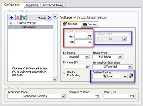
Note: Verify the custom scale is applied and the new Scaled Units are displayed correctly, shown above in blue.
This scale is convenient for directly assigning Pre-Scaled Values to their corresponding Scaled Values, where the maximum and minimum Pre-Scaled Values are +/- the transducer's Rated Output (R.O.) in Volts.
Ex: A 100 lb tension/compression load cell with a 2 mV/V R.O.
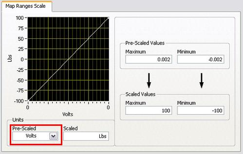
Note: Remember to verify a custom scale is selected and the new units appear as expected in the DAQmx task as shown in blue in the task configuration.
A Table Scale can be used similar to a Map Ranges Scale by directly assigning the Scaled Values. However it can also be used to input the calibration values from the Certificate of Calibration provided with the transducer.
Ex: The Certificate of Calibration for a load cell lists the load as -100 lbs and the mV/V as -1.95, as well as, 100 lbs and 1.98 mV/V.
Select Add and enter - 0.00195 for Pre-Scaled and -100 for Scaled. Repeat for the next set of values with .00198 for Pre-Scaled and 100 for Scaled.
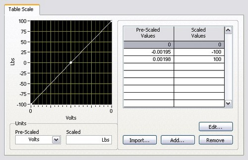
Note: Remember to verify a custom scale is selected and the new units appear as expected in the DAQmx task as shown in blue in the task configuration.