Solution
The NI-9237 is a bridge and strain measurement module. It can be configured for quarter, half, and full bridge measurements for both 120Ω and 350Ω bridge completion. Accessories are needed for quarter bridge measurements (see
Quarter Bridge section below). A shunt resistor and half-bridge competition resistors are built into the NI-9237.
This module is designed for Wheatstone bridge measurements as seen in the image below:
It is important to note that the numbering of the Wheatstone bridge arms is not arbitrary. The resistor values are used in complex equations to calculate the strain or expected voltage. The resistor name definition can be summarized as follows:
- R1 is defined between EX + & AI -
- R2 is defined between EX - & AI -
- R3 is defined between EX - & AI +
- R4 is defined between EX + & AI +
The NI-9237 has 10 pins for each channel. These pins, with either the DSUB connector or the NI-9949 accessory, correspond to:
| Pin 1 | SC | Shunt Resistor end 1 |
| Pin 2 | AI+ | Channel Input + |
| Pin 3 | AI- | Channel Input - |
| Pin 4 | RS+ | Remote Sense + |
| Pin 5 | RS- | Remote Sense - |
| Pin 6 | EX+ | Excitation + |
| Pin 7 | EX- | Excitation - |
| Pin 8 | T+ | TEDS+ |
| Pin 9 | T- | TEDS- |
| Pin 10 | SC | Shunt Resistor end 2 |
Below we illustrate the external connections necessary to take measurements from various types of strain gauges and the external connections needed for shunt calibration.
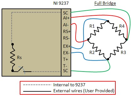
Full Bridge:

- Note: We can see the internal shunt resistor (Rs). It does not matter which SC pin is connected to which side of R3. When shunt calibration is being performed, the internal switch closes to connect the resistor. During normal operation of the module, the switch remains open.
- Note: You can use remote sensing to continuously and automatically correct for errors in excitation leads which generally is most appropriate for half- and full-bridge sensors. Connect remote sense terminals (RS+ and RS-) to the points where the excitation voltage wires connect to the bridge circuit. For additional details on the remote sensing, configuration refer to the NI-9237 Datasheet.
- Note: You can program the NI-9237 to supply 2.5 V, 3.3 V, 5 V, or 10 V of excitation voltage. The maximum excitation power for internal excitation is 150 mW. If you need to supply higher than that, please use external excitation, for additional details on how to configure it please refer to the following article: Use External Excitation with the NI-9237 Module.
- Note: If your strain gauges only has 4 wires, then you do not need to connect the two wires for shunt calibration.
- Note: The NI-9949 accessory can be used with the NI-9237 RJ50 front connector as a feed-through terminal adapter.
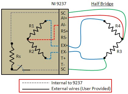
Half Bridge / QuarterBridge II:

- Note: We can see the NI-9237’s internal bridge completion resistors. EX+, EX-, and AI+ will still need to be connected by the user.
- Note: Quarter Bridge II configuration is connected to the NI-9237 as if it were a Half Bridge. R4 is the active quarter bridge strain gauge. R3 is a dummy resistor placed perpendicular to the direction of strain, and will therefore exhibit changes in resistance only due to temperature drift. When configuring the strain measurement task in software, you will need to select Quarter Bridge II in the task setup.
- Note: The NI-9949 accessory can be used with the NI-9237 RJ50 front connector as a feed-through terminal adapter.
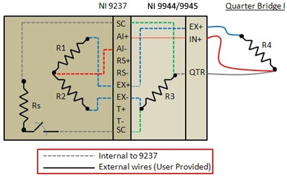
Quarter Bridge:

- Note: You can use the NI-9944 (120Ω nominal resistance), NI-9945 (350Ω nominal resistance), and NI-9926 (1kΩ nominal resistance) for Quarter Bridge completion. For the NI-9944 and NI-9945, no external connections are necessary for shunt calibration because the NI-9944 and the NI-9945 make those connections internally. Review the following articles for more information: