This measurement is known as Two-Signal Edge-Separation. The following two requirements must be met in order to create a Two-Signal Edge-Separation task:
- The two signals must be in start-stop order.
- The rising edges must be sufficiently separated to make a measurement.
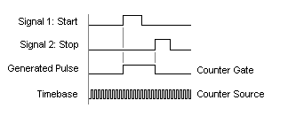
A pulse is generated using the 2 signals that you specify. If you tell the task to use the rising edge of both signals, then the generated pulse will go high on the first rising edge and back to low on the second rising edge. This pulse is then used as a gate signal, and an internal timebase is used as a counter source signal. Therefore, the internal timebase is only counted for the time between those 2 rising edges. Using this count, the actual time between edges can be returned. See the figure below for a visual.

As an alternative, a signal other than the internal clock can be counted. In order to do this, use a property node which will explicitly define the signal for the “source.” Select
Functions Palette » Measurement I/O » DAQmx » DAQmx Advanced » DAQmx Constants & Property Nodes » Channel Node. After wiring in the task, click Property from the new property node and select
Counter Input » General Properties » Counter Timebase » Source from the drop down menu. The new input on the property node will allow you to wire in the new source signal.
Hardware Setup
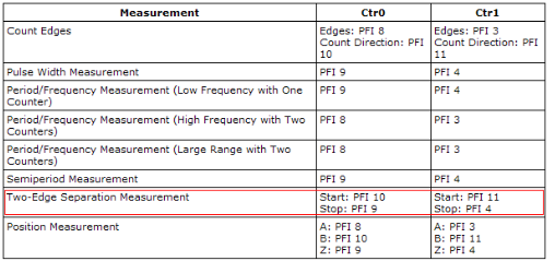
The Two-Edge Separation method uses specific PFI lines to generate the start and finish pulse.
To identify which lines will be used, access the DAQmx Help:
Go to
Start » Programs » National Instruments » NI-DAQ » Documentation » NI-DAQmx Help. Then search for “Two-Edge” and click the help file named
Measuring Period, Semi-Period, Pulse Width, and Two-Edge Separation. Go to the bottom of the help file and select “Making Signal Connections”.
Now select your device. You should see a table that looks like this:

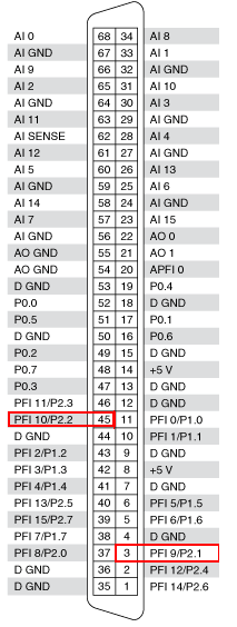
To find out what pins line up to the PFI lines, either go to Measurement & Automation Explorer (MAX) or check the pinouts in your device's user manual. In MAX, find your device under DAQmx devices, right click it and select
Device Pinouts. This should then bring up a help file which shows which PFI lines are linked to the specific pins. For example, on a PCI-6259 the PFI line 10 refers to pin 45 and PFI line 9 refers to pin 3 as shown here:

Connect these to your Start and Stop trigger. You can also modify the terminals used for each signal by using the DAQmx Channel Property Node.vi. For example, to change the input terminal for the first signal, add a DAQmx Channel Property Node.vi after creating your task and change the property found under
Counter Input » Two Edge Separation » First » Input Terminal. Make sure the property is in Read mode and wire the desired terminal to its input.
Additional Information
Examples of Two-Signal Edge-Separation are available in the NI Example Finder (
Help» Find examples...). Click on
Browse » Hardware Input and Output » DAQmx » Counter Input » Counter - Read Pulse Width and Frequency (Continuous. vi) or Browse » Hardware Input and Output » DAQmx » Counter Input » Counter - Read Pulse Width and Frequency (Finite). vi. Although these examples seemingly only pertain to Pulse Width and Frequency measurements, they include a Two-Signal Edge-Separation example as well.
Note: If you would like to directly measure frequency without a conversion from pulse separation, you will need to use a Counter Input.