Solution
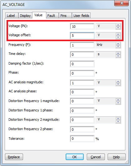
The difference between the multimeter and measurement probe RMS measurement is that the multimeter removes the DC signal while the measurement probe includes the DC signal in the calculation. For example, an AC Voltage Source was set to 10Vpeak and 5V DC offset as shown below:
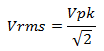
To calculate RMS the following equations are given:
Sine wave:
Sine wave with DC offset:
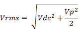
Applying the Vpk and DC offset voltage to the above equations we get:
Sine wave Vrms = 7.07 V
Sine wave with DC offset Vrms = 8.66 V
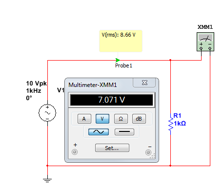
The image below shows the simulation results from Multisim. The multimeter shows 7.07 V which means the DC offset was removed from the calculation. The measurement probe shows 8.66 V and that means DC offset was included in the calculation.
When you measure RMS for non sine-wave signals such as a half-wave or a square wave use the measurement probe because those signals often have DC components.