Solution
Phase-locked loop (PLL)A phase-locked loop (PLL) is a feedback circuit designed to allow one circuit board to synchronize the phase of its on board clock with an external timing signal. PLL circuits operate by comparing the phase of an external signal to the phase of a clock signal produced by a voltage controlled crystal oscillator (VCXO). The circuit then adjusts the phase of the oscillator’s clock signal to match the phase of the reference signal. Thus, the original reference signal and the new signal are precisely in phase with each other.
A good visual example of this is shown in the following
figure 1 from the
X Series manual.
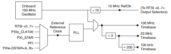 Figure 1.
 X Series Timing Sources
This block diagram shows how the PLL is used to derive the rest of the timing signals in the X Series DAQ devices.
Figure 2 shows a block diagram of the PLL that is used on the M Series DAQ devices.
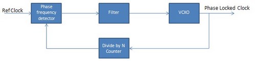 Figure 2.
 PLL Block Diagram
The actual programming techniques required to synchronize the sample clocks of multiple boards through a phase-locked loop depends on the type of hardware in use. With PCI-based products (X Series PCI DAQ boards, PCI digitizers, etc.), all synchronization is conducted by sharing signals through Real Time System Integration (RTSI) timing and trigger lines connected by a RTSI cable. In this scenario, one board will operate as the master and export its internal clock over a RTSI line to the slave boards.
With PXI-based products the same method can be applied as is used with PCI cards, however, PLL synchronization is more commonly conducted by synchronizing each board’s clock to the PXI Chassis 10 MHz clock, which is built in to the backplane of the chassis and accessible through PXI Trigger lines. For instrument-specific information on phase locked looping, see the links below.