Solution
The method you will use to set the power-up state of the digital lines will depend on which DAQ device you are using.
X Series (STC-3)From the
X Series User Manual:
"At system startup and reset, the hardware sets all PFI and DIO lines to high-impedance inputs by default. The DAQ device does not drive the signal high or low. Each line has a weak pull-down resistor connected to it, as described in the specifications document for your device."
NI-DAQmx supports programmable power-up states for PFI and DIO lines. Software can program any value at power up to the P0, P1, or P2 lines. The PFI and DIO lines can be set as:
• A high-impedance input with a weak pull-down resistor (default)
• An output driving a 0
• An output driving a 1
Refer to the
NI-DAQmx Help or the
LabVIEW Help for more information about setting power-up states in NI-DAQmx or MAX."
M Series (STC-2)All M-series devices have programmable power-up states which can be configured either in Measurement & Automation Explorer (MAX) or LabVIEW. Please refer to
What is Digital Output Line Power Up State and How to Set It and Read Back from EEPROM? for more information.
E Series, S Series (STC)The E series and S series devices have a default high impedance input power-up state for all digital lines. The lines are pulled high by an internal pull-up resistor (resistance can vary between 17 kΩ and 100 kΩ).
To change the power-up state to a logic level low, a resistor can be wired between that digital line (DIOx, where x is the line number) and digital ground (DGND). Assuming the worst case scenario (17 kΩ internal pull-up resistor), you should choose a pull-down resistor with an impedance of less than 3.2 kΩ. Thus, the device would require <2 mA to drive the pull down circuit to TTL low (0.8 V), leaving 11 mA for the load (E series devices can source up to 13 mA).
Note: Some devices, such as the PCI-6025E or the AT-MIO-16DE-10, have 3 additional ports of digital lines. On these devices Port 0 uses the DAQ-STC chip, but ports 2, 3, and 4 use the 8255 chip. The digital lines of the 8255 chip consist of +5 V connected to a 100 kΩ pull-up resistor. Thus, it is necessary to apply a different value for the pull-down resistor on the 8255 digital lines.
You can find the formula and information regarding these lines in the PCI-DIO-96/PXI-6508/PCI-6503 User Manual. The PCI-DIO-96, the PXI-6508, and the PCI-6503 boards are digital I/O boards that use the 8255 chip, so the information regarding the chip is available in the manual.
USB-6008/6009/6501These USB devices have a default power up state of a high impedance input or alternatively called open collector/open-drain.
To set other values on the DIO lines, it must be statically updated by Software after power up of your system. If you have a need for programmable power-up states in your application, please look for this feature in
other NI product lines.
Note: Because the internal pull-up resistor on these USB devices is small (4.7 kΩ) to pull the voltage below 0.8V, a pull-down resistor of 850 Ω or less is required. With such a small resistor ~6 mA will be pulled from the device when driving the line high with no load connected. Since the device can only supply up to 8.5 mA, that only leaves ~2.5 mA for the load. It is therefore not recommended to use this method to pull the voltage down to a low state.
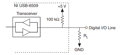
USB-6509The NI USB-6509 facilitates user-configurable pull-up or pull-down tasks. Each DIO channel is connected to a 100 kΩ resistor and can be pulled high or low using the back-panel switch. Using this switch pulls all 96 DIO lines high when set to HIGH or low when set to LOW. However, if all lines are high, you might want to pull some lines low.If you select the pulled-high mode, each DIO line is pulled to Vcc (+5 V) with a 100 kΩ resistor. To pull a specific line low, connect a pull-down resistor (RL) whose value gives you a maximum of 0.8 V between the line and ground.

Figure: DIO Channel Configured for High DIO State with External Load (Pull-Down Resistor)
Other Digital I/O DevicesNI offers a wide variety of Digital I/O devices with features such as channel isolation, high voltage, dedicated hardware timing, etc. (e.g. NI 653x, 651x).