There are two ways to programmatically reset a CompactRIO controller.
- Using the RT Reboot Controller VI
- Using the FPGA
- CompactRIO controllers have a System Reset digital line which resets the controller when set to true. See below for more information on how to use the System Reset line
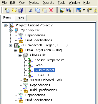
LabVIEW 8.5 and laterThe System Reset digital line is automatically added to the project when the CompactRIO controller and FPGA backplane are added to the project. You can drag this digital line into the block diagram of your FPGA VI to create an I/O node and wire a
true constant to its input to reset the CompactRIO controller. The image below shows a LabVIEW 8.5 or later project with the System Reset I/O item.

LabVIEW 8.2 and 8.0
To add this digital I/O item in LabVIEW 8.x, complete the following.
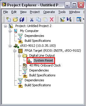
- Right-click the FPGA target in the Project Explorer window and select New»FPGA I/O from the shortcut menu to display the New FPGA I/0 dialog box.
- Expand the Digital Line Output item, select System Reset, and click the Add button.
- Once added to your project, you can drag this I/O node into the block diagram of your FPGA VI and wire a boolean true to its input to reset the CompactRIO controller.
The image below illustrates a LabVIEW 8.2 or 8.0 project with the System Reset I/O item.

LabVIEW 7.1
To add this digital I/O item in LabVIEW 7.1, complete the following.
- Target LabVIEW to the FPGA device and open your FPGA project.
- Place a Digital Output I/O Node on the block diagram.
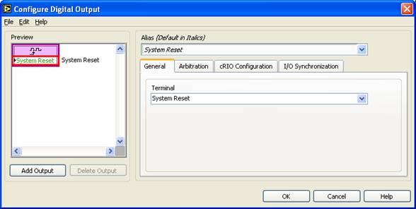
- Double-click the I/O node to open the Configure Digital Output dialog box.
- In this window, under the General tab, select System Reset as the specific terminal from the drop-down menu. Close the Configure Digital Output dialog box.
- Wire a Boolean true constant to the input of this I/O node to reset the CompactRIO controller when the I/O Node is executed.
The Configure Digital Output dialog box is shown in the image below.
