Solution
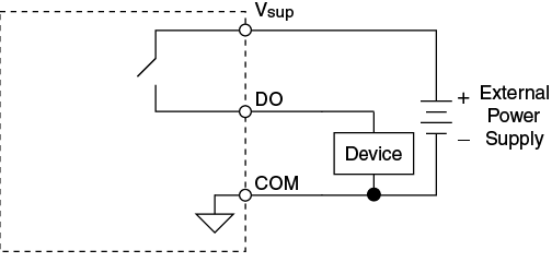
When the outputs are set low on the NI 9375, 9472, 9474, 9476, and 9475 to High or Low, the channel does not toggle between Vsup and COM. It toggles between Vsup and a high impedance state where the high impedance state has an unspecified leakage current. This behavior is expected because the output voltage is not pulled down to the value of the COM (about 0V) at a low level, but from the equation "output voltage (Vo) = Vsup - (Io x Ro)" which can be found in the datasheet of most of the above devices.

When using a device that has a larger than typical impedance (>1MΩ) this creates a voltage drop across the device that may cause the device to turn on.
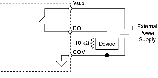
In order to interface the NI 9375, 9472, 9474, 9476 & 9475 with a device expecting Vsup or ~0 volts (like 9411), you must use a pull-down resistor to bring the high impedance lines to ground. A standard value of 10 kΩ between DO and COM, as shown in the image below, will work in most cases. To ensure a specific voltage when DO is off, follow the steps provided.

To calculate the maximum value of the resistor (Rp) needed:
1. Measure the current (I) through the device when the Digital Output line is off
2. Determine the resistance of the device (Rd)
3. Determine the lowest voltage (V1) that will not turn the device on when Digital Output is off
4. Solve for Rp=(V1*Rd)/(I*Rd-V1) This equation does not yield a negative or infinite Rp when V1<I*Rd. It is recommended to choose an Rp less than this calculated value to allow for process and temperature variations in leakage current.