Additional Information
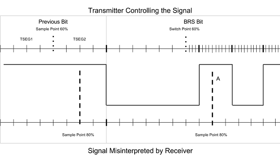
BRS denotes the point in the CAN frame where the bit rate is switched from the nominal rate (used for the Arbitration ID and header) to the data rate. A transmitter will send the BRS as a recessive bit until the sample point, at which it immediately switches the data rate.
It is imperative that the sample point of all nodes match since the data bit rate is usually much higher than the nominal rate. If the nominal rate sample point does not match with another node, many data bits can be transmitted early or misinterpreted during the overlap between the transmitter's sample point and that of the receivers.
For example: A transmitter and receiver are configured with a data bit rate that is 4X the nominal bit rate. The transmitter sends a frame with a nominal rate sample point of 60% to a receiver with a sample point of 80%. At the sample point, the transmitter will switch to the faster bit rate while the receiver is still waiting to sample the signal. The transmitter then continues with the rest of the frame and the receiver may read an indeterminate value or an incorrect value (A). The sample points for the remainder of the data will continue to be offset and errors will ensue.
CAN in Automation (CiA) is the international users' and manufacturers' group that develops and publishes recommendations for CAN FD. The bit rate timing values used by the default XNET baud rates were selected based on CiA recommendations, reliability testing, and the results of plugtest participation. Some device manufacturers may choose to operate with settings that differ from the XNET defaults. To avoid a BRS mismatch with other devices, care must be taken to ensure all devices on the cluster are operating with the same bit timing settings.
NI-XNET 16.1 and later includes a simple graphical utility in the bus monitor to help determine the hexadecimal values needed for a specific sample point. This utility can be accessed by opening the
NI-XNET Bus Monitor, navigating to
Settings» Interface and
Database... to open the interface and database settings. Then from the
Baud Rate drop-down, choose the
<Custom> option. This will result in the dialog below, from which the
Sample Point slider can be used to adjust the sample point while keeping the pre-selected baud rate. Once a proper sample point has been selected, you can copy the hexadecimal
Custom Baudrate, which is the same value used for the properties discussed above.
The below is frequently used Baudrate specification with 80% sample point. For more exact values, please refer to ECU's specification or reach out to the manufacturer.
- CAN Baudrate : 500k, 32A0071E07(HEX)
- BRP 1
- SJW 7
- TSEG1 30
- TSEG2 7
- CAN FD Baudrate : 2M, 800F00A0032E33 (HEX)
- BRP 0
- SJW 3
- TSEG1 14
- TSEG2 3