Solution
- Using a SPST switch, one method to connect this circuit is to add a resistor and connect the circuit as shown below. When the switch is closed, the AND gate input is connected to ground giving you a low. When the switch is opened, the input is connected to Vcc through the resistor giving you a high input.
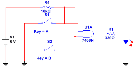
Note : The model of a SPST switch is made up of two resistors; double-click the switch to open the component properties dialog to view its properties. When the switch is opened, the resistor is represented by Roff which is 100 MΩ, and when the switch is closed the resistor is represented by Ron which is 100 µΩ. In your circuit, regardless of the switch position, the AND gate input is 5V and this is why the output is always high. In the real world, when the switch is opened, there is no real voltage applied to the gate input and it said to be floating. Usually, the input floats towards a high but any noise can cause the input to go low; therefore, this circuit is unpredictable.