To add holes to the footprint, you need to be in the Ultiboard
Footprint Edit Mode. For information to get into this mode, please refer to the
Creating a Custom Component in NI Ultiboard tutorial.
You need to decide what type of mounting hole you want:
- A hole with a copper ring around it
- A hole without any metal attached
Before adding any holes to the footprint, create the footprint as usual like adding pads, silkscreen information, 3D information, RefDes, and so on.
Adding a Hole With a Copper Ring Around It
- Place»Pins, select THT Pin and then click OK.
- A through hole pad is attached to your mouse, move your mouse cursor to the appropriate location and left-click to drop the pad.
- Double-click the pad on the workspace and then select the Pads tab.
- Enter the value for the drill hole diameter and also the annular ring.
- Note: The drill diameter you enter will determine the drill bit size, however, during manufacturing, the hole wall will be fill with metal and therefore, your final hole will be a little smaller, you should add some tolerance for your drill diameter.
- For additional holes, repeat the above steps.
Adding a Hole Without Any Metal Attached
- Place»Hole.
- Select the Hole tab, enter a value in the Radius field for the hole and click OK.
- Move your mouse cursor to the appropriate location, left-click to place the hole on the workspace.
Saving to Your DatabaseOnce you have added all the holes to your footprint select
File»Save to Database to save the footprint to your database.
Additional Information
The hole you placed will not appear in the 3D view by default. If you want to see a hole in 3D view, follow the steps below:
Display in 3D View
- Double-click 3D info Top in the Design Toolbox to make it the active layer.
- Select Place»Graphics»Circle.
- Draw a circle that is the same size as your hole and place it directly over the hole.
- Double-click the circle you just placed.
- If your circle is completely filled, click on the General tab and select the outline shape in the Style field
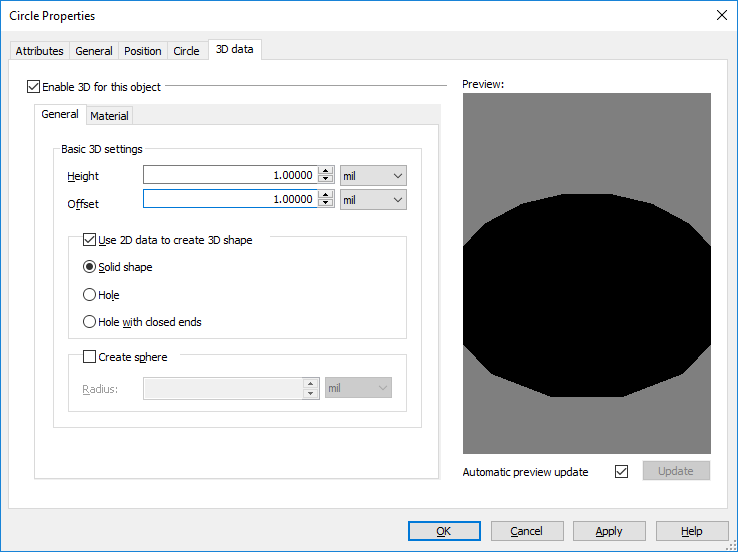
- Select the 3D Data tab and enter information as shown below:
 Click on the Material tab.
- Click on the Illumination box and select the gray color from the color palette. In the 3D view, the default background color is gray; by changing the 3D object to same color we will create an illusion that there is a hole on the board.
- Change your active layer to 3D info bottom in the Design Toolbox. Repeat step 2 to 8 to add information to your 3D information on the bottom layer.