You can find this information in Measurement and Automation Explorer (MAX) or in LabVIEW using the Wire Mode attribute.
MAX
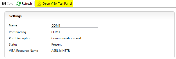
Follow the instructions below to access the Wire Mode in the Attributes tab of the VISA Test Panel.
- Open NI MAX from the Start Menu.
- Expand Devices and Interfaces and select the serial port of interest. For remote devices, expand Remote Systems >> <Your Device> >> Devices and Interfaces.
Note: If you are unable to see the serial port on your device, refer to
Serial COM Ports Missing in MAX or LabVIEW.
- Select Open VISA Test Panel.

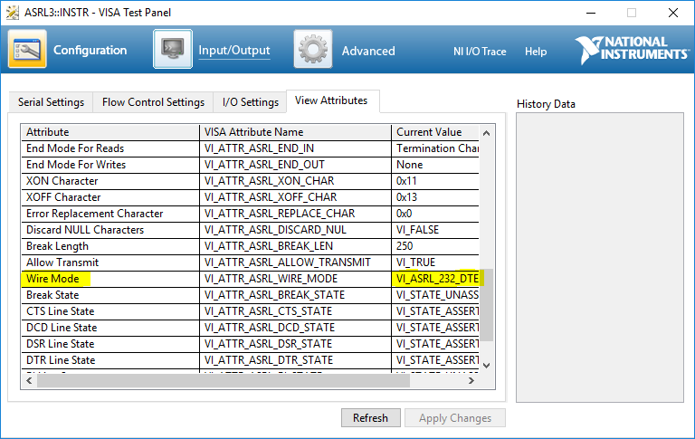
- In the Test Panel, select the Configuration option and open the View Attributes tab.
- In the left column, search for the attribute Wire Mode. The Current Value listed in the right column is the serial port’s current protocol and wire configuration. For more information about the different wire modes, refer to Transceiver Modes on NI RS-485 Serial Cards.

LabVIEW
This option allows you to programmatically read the Wire Mode attribute from different or multiple ports. Follow the instructions below to access the Wire Mode using a VISA property node.
- Add a VISA property node on your block diagram.
- Wire the VISA serial session of the port of interest to the reference input. Alternatively, you can right-click on the reference input, create a constant or control, and select the port of interest.
- Select Property >> Serial Settings >> Wire Mode to configure the property.
- Right-click on the Wire Mode output to create an indicator. Refer to Serial Settings: Wire Mode to see the possible output values.

Additional Information
To change the protocol or transceiver wire mode of the serial port, refer to
Setting the Transceiver Wire Mode of Ports on NI Serial Boards.
Note: Check the user manual of the device you are using to determine what protocol and wiring modes are supported for the port. The property node may present more options than are applicable for your port.