Solution
In the NI-SWITCH Soft Front Panel, you can test your relays by
Schematic or by
Relay.
Using the schematic option is usually easier since the connections are visually shown.
Schematic mode:
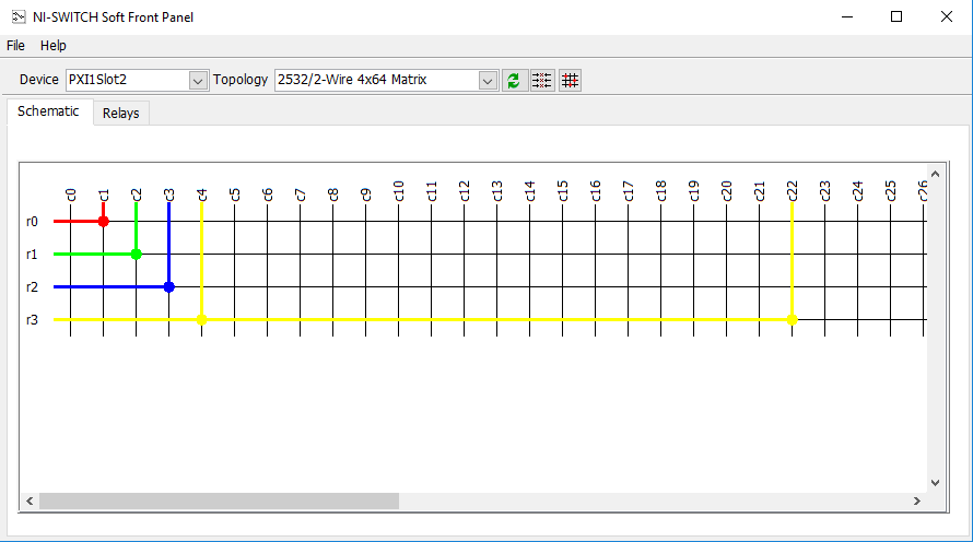
When using the
Relay mode, you can see the opened or closed relays individually by their name. These names are not mapped directly to the visual representation in the Schematic mode (Although they are equivalent, closing a relay in Schematic mode, closes the relay in the Relay mode). The relay names are set by the bank configuration for each individual NI-Switch module. This bank configuration can be consulted in the
NI Switches Help and it is different for each supported topology.
Relay Mode:
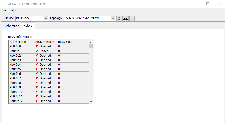
Matrix cards work with banks to create the different topologies, the
kb initials mean the bank,
r is for the row and
c is for the column. As an example, for the PXI/PXIe-2532/2532B 2-Wire 4x64 Matrix topology the
bank diagram is the following:
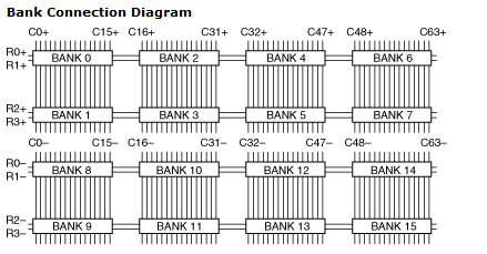
For this topology, since it is 2 wire, we have a positive and a negative connection. Bank 0-7 for the positive and Bank 8-15 for the negative as the Columns indicate on the image above. Meaning that selecting a relay route will actually close 2 relays.
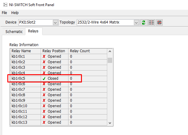
If you were to select a row 2 and column 5 route:
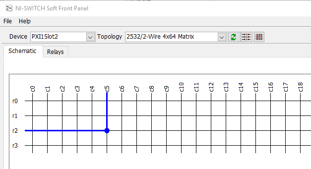
The relay name would be:
- kb1=Bank 1
- r0=Row 2 of bank 1 is 0
- c5=Column 5
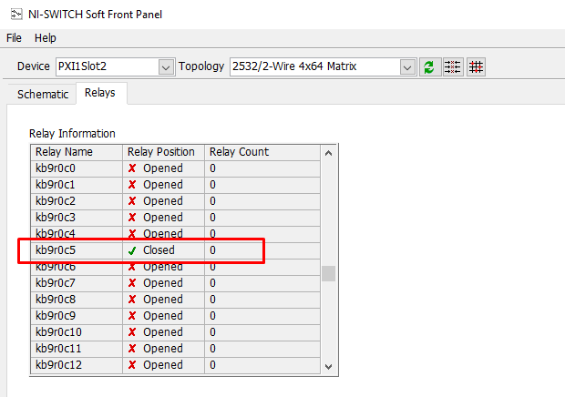
- kb9=Bank 9
- r0=Row 2 of bank 9 is 0
- c5=Column 5
Relay name:
kb1r0c5 and
kb9r0c5 since this is a 2-wire network topology.