The counter functionality of any PCI(e) or PXI(e) Counter or Timer card or USB-6xxx Multifunction I/O device with inbuilt counter can be tested by using the Counter I/O tab in its NI MAX Test Panels. We will refer to the PCI(e) or PXI(e) card in the steps below. However the same steps apply to USB device as well.
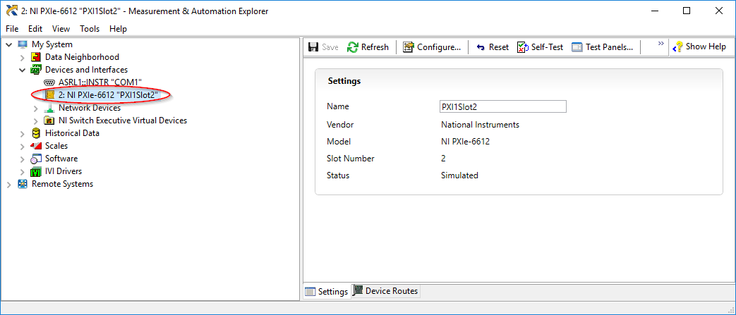
1. Open NI MAX and see if the card shows up. We can use any PXI chassis and controller for this.
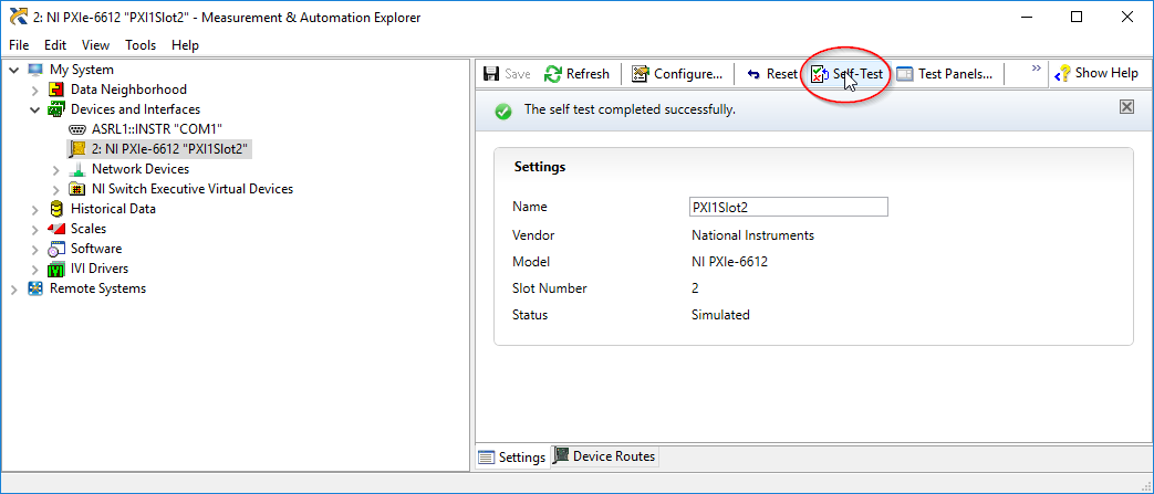
2. Select the card in NI MAX and click on Self-Test
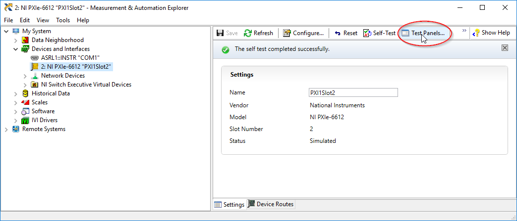
3. Click on Test Panels
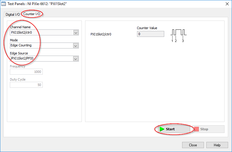
4. Use the Counter I/O tab to test the card’s internal counters. Use the Channel Name to select the counter to test. These counters will be internal hardware devices that the card has, not physical ports/terminals.
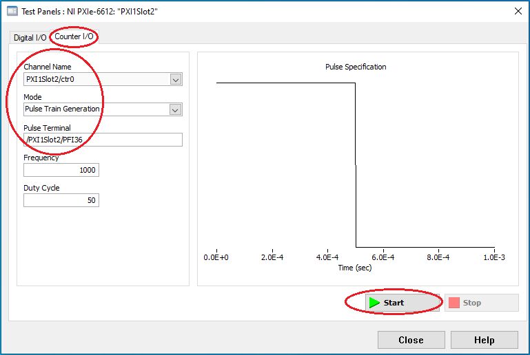
5. Select the type of measurement to do under Mode- Edge Counting to make sure the counter works as an input device or Pulse Train Generation if you’re interested in measuring the output capabilities.
- For an Edge Counting task, select the physical pin that you want to use to test your card under Edge Source. You can use the PFI lines* to wire a pulse train, or an encoder signal and check if the counter displays the edges counted. Remember to press Start to acquire the pulses.
- For a Pulse Train Generation task, you will need to use the default pin for the specific counter**. For example, the default terminal for counter 0 is PFI 36 in the NI 6612. Remember to press Start to generate the pulses.
*Note: Refer to the card’s specifications to find the mapping between the PFI lines and the physical ports. For example, PFI 1 maps to pin 44 of the NI 6612.
**Note: When using Test Panels for a Pulse Train Generation task, you will not be able to change the Pulse Terminal.
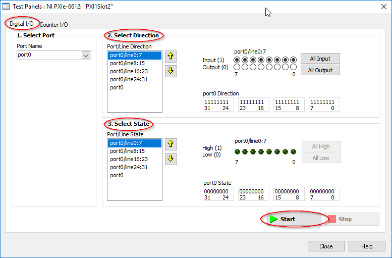
6. (If your card has Digital IO) Use the Digital I/O tab to test the card’s digital lines. The Select Direction indicates if the port will be input or output, and the Select State section will display the input or allow changing the output (depending on the direction selected for the pin). Remember to press the Start button to generate the digital signals.
Additional Information
The card can also be tested with LabVIEW by following the steps below:
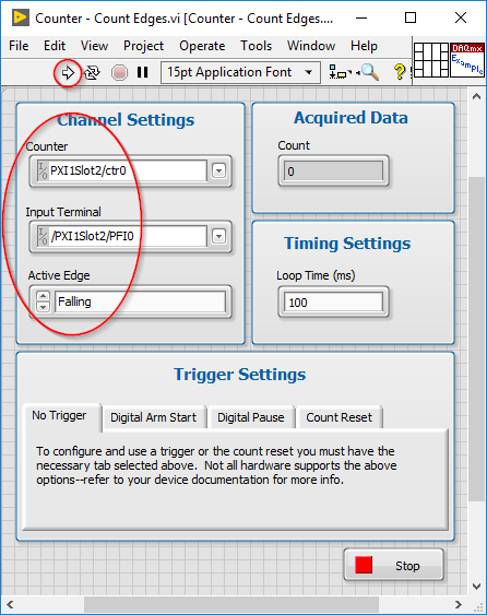
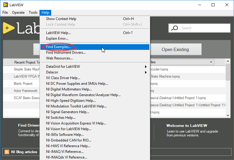
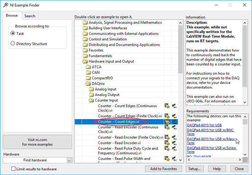
1. Open LabVIEW and go to the Help -> Find Examples
2. In the NI Example Finder, navigate to Hardware Input and Output > DAQmx > Counter Input > Counter – 'Count Edges .vi'
3. Use the same configuration used in step 5 of the solution section and run the example to validate functionality.