Solution
NI specification documents specify the DC accuracy in terms of a percent of the input voltage plus a small voltage offset. If you need the actual voltage range of the DC accuracy for a given input value, then you will need to perform the calculations as shown below.
Expected Voltage Calculation
The DC accuracy for a given applied voltage at the input of a NI Digitizer/Oscilloscope is given by the equation:
DC Accuracy = ± (Gain Error * Applied Voltage + Offset Error)
The expected measured voltage for a given applied voltage at the input can be calculated by applying the following formula:
Expected Voltage = Applied Voltage ± DC Accuracy = Applied Voltage ± (Gain Error * Applied Voltage +Offset Error)
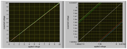
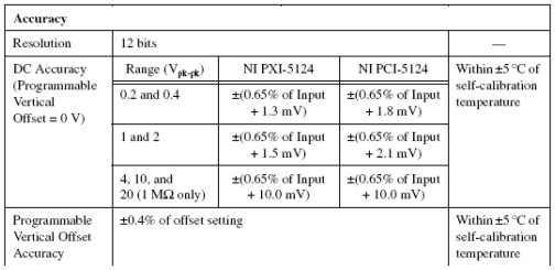
As an example, take a look at the figure for the DC accuracy of a NI PXI-5124. If we have configured the digitizer to use the 10 Vpk-pk range, then 0.65% corresponds to our Gain Error and 10.0 mV corresponds to our Offset Error. If we then apply 7.95 V to the input, our expected voltage will be:
Expected Voltage = 7.95 ± (0.0065 * 7.95 + .01) V = 7.95 ± 0.061675 V
You can see how the right graph on the figure below shows that if you applied 7.95 volts your expected voltage can be anywhere between the green and red line.
DC Drift Calculation
The previous calculation of the scope DC accuracy was done assuming the room temperature is within ± 5 °C of the room temperature during the last self-calibration of the device. Outside of this temperature range we need to account for DC drift. DC drift is a slow change in our accuracy due to temperature change.
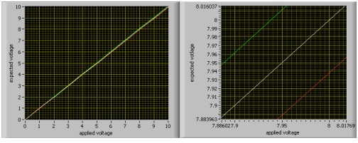
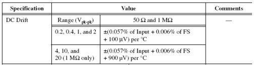
For example, assume that a PXI-5124 was last self-calibrated at a room temperature of 28 °C. However, the room temperature is now 35 °C. This would mean that we are 2 °C outside of the ± 5 °C range where we don’t need to account for DC drift. If we are still applying a voltage of 7.95 V to the device and we are still configured to use the 10 Vpk-pk range then we can see from the figure below that the DC drift can be calculated using the equation below.
DC Drift = ± (0.00057 * 7.95 + 0.00006 * 10 + 0 .0009) * 2 V = ± 0.0060315 V
To get our overall uncertainty we need to add the DC drift to our previous Expected Voltage calculation as shown below.
Expected Voltage = 7.95 ± 0.061675 ± 0.0060315 V = 7.95 ± 0.0677065 V
We can see in the figure below how the DC drift extends out the range of the Expected Voltage. The yellow and blue lines represent the uncertainty attributed to both the accuracy and the DC drift.